One line, many brands.
A co-packer runs constant temperature milk and tea-type beverages on the same front end, feeding an aseptic carton filler and a PET rotary filler. The line was designed around product changes, not around nameplate capacity.
- Client
- Jiangsu Xianshiduo Food Technology Co., Ltd. (Jiangsu, China)
- Scope delivered
- Blending tank farm 01#–07# · tubular UHT · vacuum deaeration · homogenisation · CIP · hot-water set · valve matrix · electrical & control
- Filling lines served
- Aseptic carton + PET rotary
- Photos
- All photos from the client's plant floor, unretouched
A co-packer buys changeover speed, not litres.
The client produces for multiple brands. Every brand brings its own recipe, sugar level, sterilisation duty and package — so switching products is not the exception on this line, it is the operating mode. And every switch means a full clean: residue means taint, colour drift or cross-contamination, and a failed customer audit costs the next order, not just one batch.
What this meant for the design
Three consequences drove the layout: each tank keeps an independent fill, discharge and cleaning circuit; the ring main with a branch valve matrix keeps different products out of shared pipe segments; and the line was built to the client's audit regime (HACCP / ISO 22000 / GMP expectations), because on a co-pack floor the audit pressure is daily, not an annual event.
The line, in four frames.
All photographs were taken in the client's plant during operation. Nothing is a render and nothing was staged for this page.
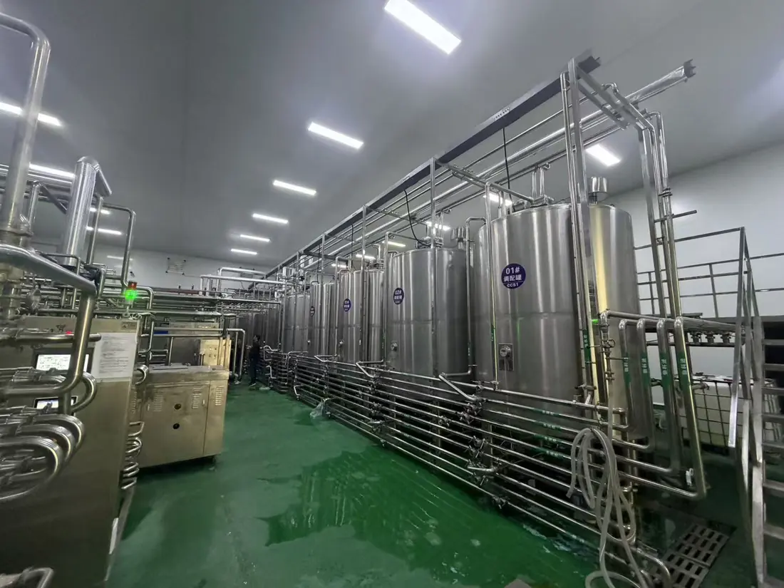
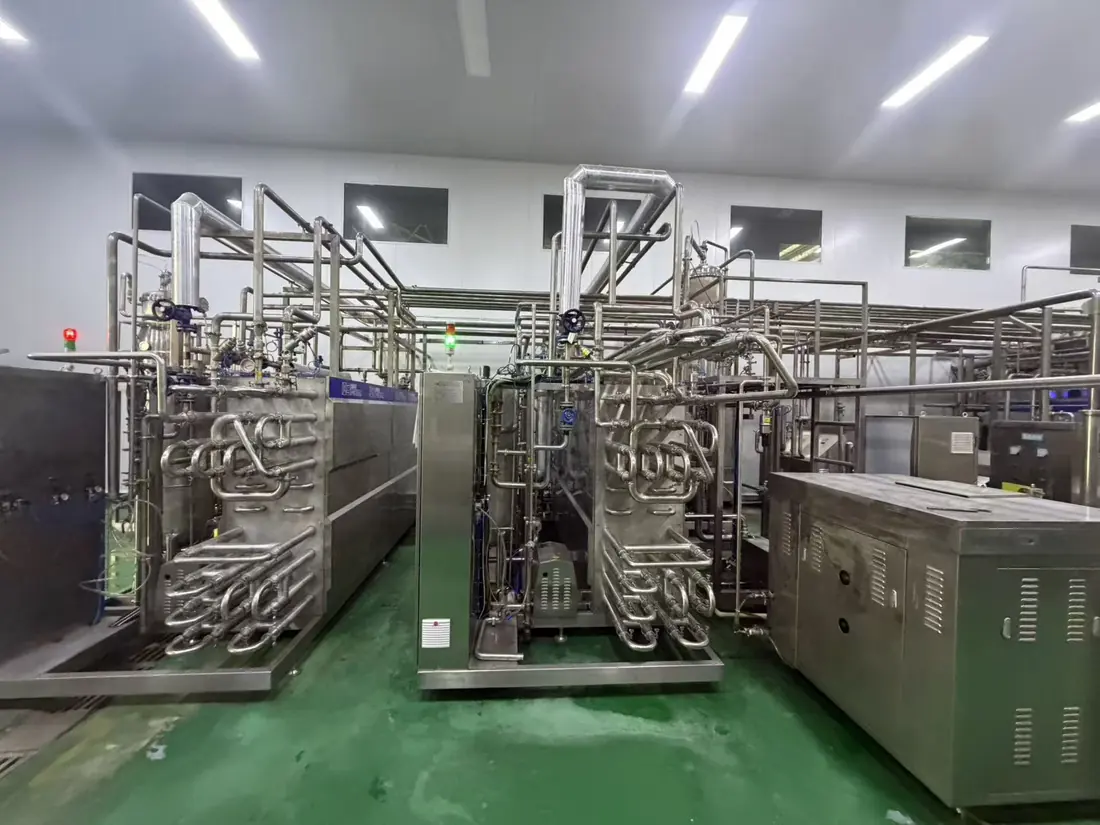
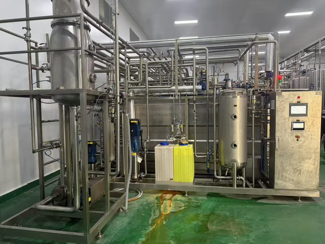
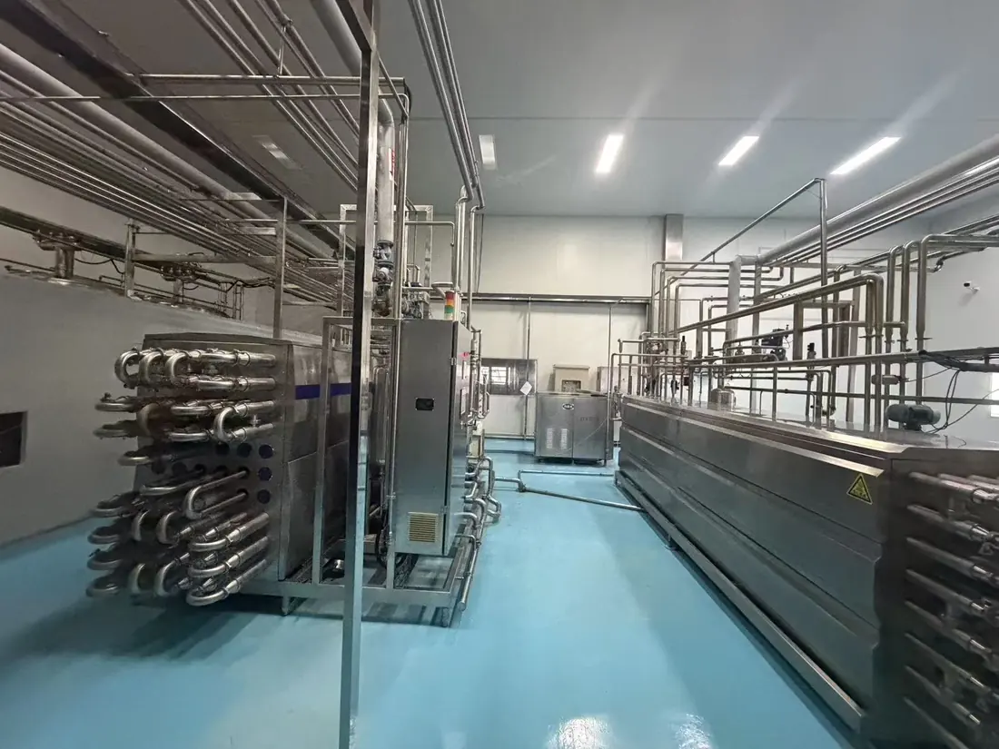
From the tank farm to two fillers, without either one waiting.
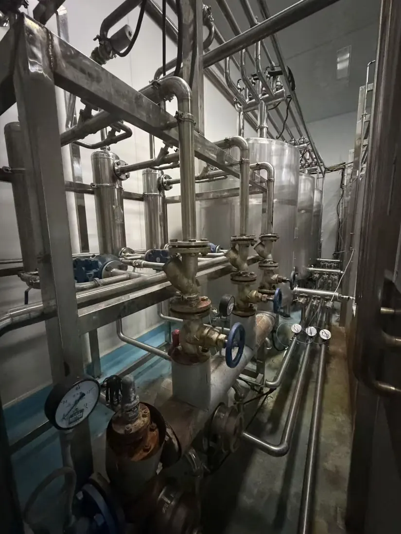
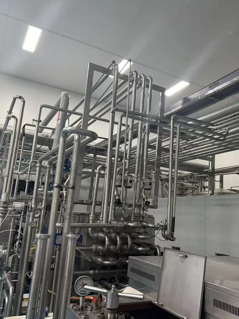
Seven blending tanks feed a ring main with a branch valve matrix, so products travel to the heat-treatment chain in assigned routes instead of queueing in shared pipe. Tubular UHT handles the pressure and viscosity duty and opens up wide for cleaning; vacuum deaeration pulls dissolved oxygen down so tea colour and aroma hold; homogenisation pressure is adjusted inline for dairy and pulped recipes. All three units run on one control logic, so parameters do not drift between manually operated stages. Downstream, the flow splits to the aseptic carton filler and the PET rotary filler.
The audit question is not “is it clean?” It is “show me.”
Caustic and acid circuits run at roughly 50 °C, hot-water sanitising at roughly 82 °C — three tanks, three circuits, each with its own temperature control. Reaching temperature is the easy part: every temperature point, pressure point and valve position carries a tag number that maps one-to-one onto batch records and reports, so when a brand's auditor asks, the record comes up on the spot.
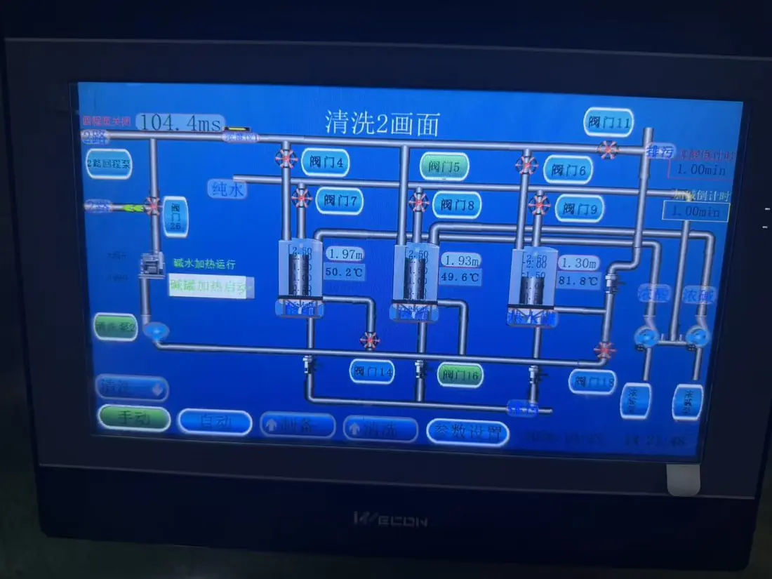
- Two screens, two states — production shows the process chain; cleaning shows valve and tank cleaning paths. Operators never mix a production state with a cleaning state.
- Drainable, dead-leg free — tank bottoms, piping and the valve matrix are laid to self-drain with no accumulation low points; headers and manways allow manual re-inspection.
- Welded sanitary connections — product-contact joints are orbital-welded sanitary fittings; no flanged dead corners, no threaded crevice points.
- Documentation pack — P&IDs, equipment list, O&M manual and batch-report templates delivered with the line, so the evidence exists before the first audit asks for it.
We replaced the segment that failed audits, not the plant.
The plant already ran. Its weakest link was an old piping segment: flanged joints with manual valves, no insulation, too many weld points — hard to clean and the first thing an auditor circles. We built and commissioned the new system alongside it, then swapped the old segment out piece by piece during production gaps. The existing tanks and both filling lines stayed in service throughout.
A note on numbers
We deliberately keep this page to what is visible and field-verifiable: the equipment scope, the photographs and the CIP set points shown on the client's own screen. Throughput, changeover times and yield figures live in the technical protocol and acceptance records — we walk through them in a call or a meeting, not on a marketing page.
Planning a co-pack front end?
Send us the product list and the filling lines you feed. We will come back with the tank count, the sterilisation duty and the cleaning concept that keeps your changeovers honest.