Four lines: tanks, sterilisers, CIP, installation.
Three equipment families, plus the installation that joins them into one section. Everything else — deaeration, plate heat exchangers, pumps, valves, instruments — is integrated to the same drawings.
- Tanks
- 500–120,000 L
- Sterilisers
- 0.5–50 t/h; 85–140 °C
- CIP
- 0.5–10 m³; 1–4 circuits
- Installation
- Piping · electrical · PLC
- Documentation
- EN 10204 3.1, FAT, DoC
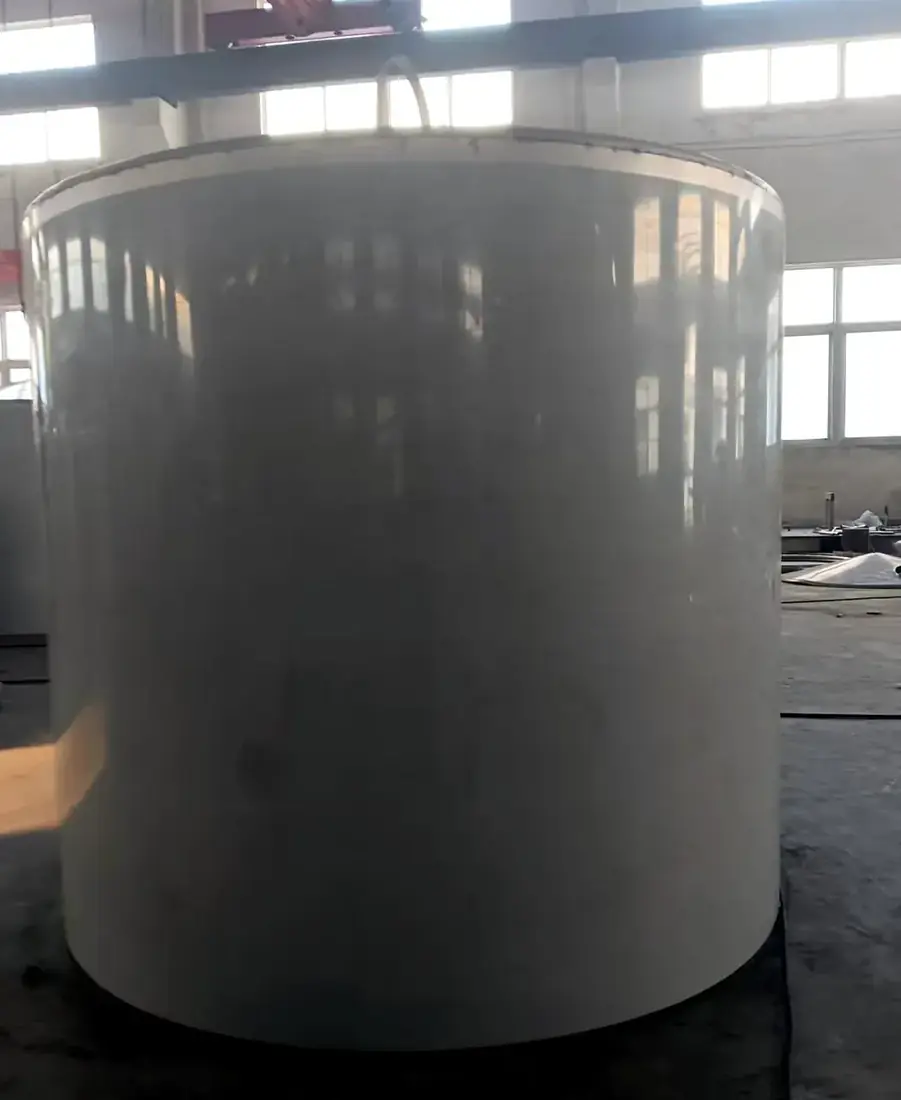
Tanks & vessels
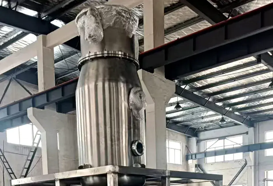
A blending tank is a tank with an agitator, not a separate product category. We build storage, blending, fermentation and high-shear vessels on the same shell standards — the difference is what goes inside and what the duty demands.
- Type follows the duty — storage, blending, fermentation, high-shear emulsifying, milk cooling. Agitation is selected on viscosity and solids, not on tank volume.
- Jacket when the process needs it — dimple or half-pipe jacket for heating, cooling and holding; three-layer construction where temperature control is part of the recipe.
- Cleanable geometry — radiused bottom, flush outlet valve and spray-ball coverage verified at commissioning.
- Batching instruments — load cells or flowmeter dosing with the ingredient sequence held in the PLC recipe.
| Type | Volume range | Installed power | Notes |
|---|---|---|---|
| Single-layer storage | 500–20,000 L | 0.55–5.5 kW | 19 standard steps |
| Double-layer storage | 500–20,000 L | — | Insulated shell |
| Double-layer agitated | 1,000–20,000 L | 0.75–5.5 kW | 14 standard steps |
| Three-layer hot/cold | 1,000–20,000 L | 1.1–5.5 kW | 14 standard steps |
| High-shear emulsifying | 1,000–5,000 L | 7.5–22 kW | Stable emulsions, gum hydration |
| Fermentation | 100–50,000 L | 0.55–11 kW | 9 standard steps |
| Outdoor storage | 20,000–120,000 L | 5.5 kW | 6 standard steps |
| Direct-cooling milk tank | 500–8,000 L | 3.6–19.6 kW | 242–1,450 kg |
Shell thickness 3 mm up to 6,000 L and 4 mm above; the national minimum of 2 mm is a floor, not a design target. Maximum shell diameter 2.3 m to pass a 40HQ door — larger volumes are segmented or site-fabricated.
| Item | Standard | Applied to |
|---|---|---|
| Product connections | OD 25–127 mm (1″–5″) | 38 mm ≤900 L; 51 mm 1,000–8,000 L; 51–76 mm above 10,000 L |
| Contact surface | Ra ≤ 1.6 µm | 0.8 µm electropolish on request |
| Product contact | SS316L | SS304 for non-contact parts |
| Certificates | EN 10204 3.1 | Plate, tube and sheet, batch-traceable |
Vessels above 30,000 L are engineered per project; the table is a volume envelope, not a fixed catalogue. Weights and lifting plans are issued before shipment.
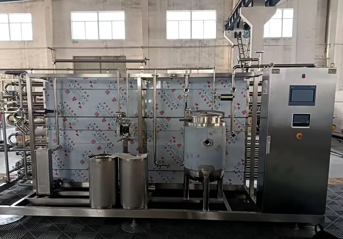
Sterilisers
Two frames, one decision: plate where the product is low-viscosity and the temperature moderate; tubular where pulp, viscosity or the aseptic requirement rules the plate out. In both cases the flow diversion valve returns product to the balance tank the moment the holding curve is not met.
Plate pasteurisation & HTST — BR series
| Application | Holding | Chain |
|---|---|---|
| Fresh milk | 85 °C / 15 s | 4 °C → 65 °C → homogenise → 85 °C → 4 °C |
| Fresh juice | 95 °C / 20 s | 25 °C → 95 °C → 90 °C → 40 °C reflux |
| Concentrate | 115 °C / 30 s | 25 °C → 115 °C → 20 °C |
| Ice-cream mix | 87 °C / 25 s | 55–60 °C → 70 °C homogenise → 87 °C → 7–8 °C |
| Sauce / seasoning | 105 °C / 20 s | 30 °C → 105 °C → 30 °C |
| Yogurt mix | 95 °C / 300 s | 5 °C → 65 °C homogenise → 95 °C → 43 °C |
Holding time and temperature are validated per product at commissioning; the curves above are standard references, not a substitute for your process authority's validation.
| Model | Capacity | Dimensions L×W×H (m) | Weight | Power | Product line |
|---|---|---|---|---|---|
| BR 0.25C-GZ-5MJ | 5 t/h | 2.0 × 1.6 × 2.0 | 1,120 kg | 3.7 kW | 38 mm |
| BR 0.25C-GZ-10MJ | 10 t/h | 2.0 × 1.6 × 2.0 | 1,320 kg | 3.7 kW | 51 mm |
| BR 0.4C-GZ-15MJ | 15 t/h | 2.5 × 2.5 × 2.2 | 2,020 kg | 7.0 kW | 63 mm |
| BR 0.4C-GZ-20MJ | 20 t/h | 2.5 × 2.5 × 2.2 | 2,220 kg | 8.0 kW | 63 mm |
| BR 0.6C-GZ-25MJ | 25 t/h | 2.5 × 2.5 × 2.2 | 2,520 kg | 11.0 kW | 76 mm |
| BR 0.6C-GZ-30MJ | 30 t/h | 2.5 × 2.5 × 2.2 | 2,720 kg | 11.0 kW | 76 mm |
| BR 0.6C-GZ-40MJ | 40 t/h | 2.5 × 2.5 × 2.5 | 3,120 kg | 11.0 kW | 101 mm |
| BR 0.6C-GZ-50MJ | 50 t/h | 2.5 × 2.5 × 2.5 | 3,500 kg | 11.0 kW | 101 mm |
Installed power excludes the hot-water set and product pump where supplied separately. Steam consumption follows inlet temperature and recovery rate, calculated per project.
Tubular UHT — BTG series
For dairy, soy, juice and tea where plate channels are unsuitable or a higher temperature is needed. The aseptic boundary sits at our outlet flange; the aseptic filler downstream is specified by you or your EPC.
| Model | Capacity | Dimensions L×W×H (m) | Weight | Power | Product line |
|---|---|---|---|---|---|
| BTG-UHT-1MJ | 1 t/h | 3.3 × 0.9 × 1.8 | 1,960 kg | 4.0 kW | 25 mm |
| BTG-UHT-1.5MJ | 1.5 t/h | 3.3 × 1.6 × 1.8 | 1,960 kg | 4.0 kW | 25 mm |
| BTG-UHT-2MJ | 2 t/h | 4.5 × 1.8 × 2.0 | 2,160 kg | 6.0 kW | 38 mm |
| BTG-UHT-3MJ | 3 t/h | 4.5 × 1.8 × 2.0 | 2,420 kg | 6.0 kW | 38 mm |
| BTG-UHT-4MJ | 4 t/h | 4.5 × 2.0 × 2.0 | 2,570 kg | 7.0 kW | 38 mm |
| BTG-UHT-5MJ | 5 t/h | 4.5 × 2.0 × 2.0 | 2,940 kg | 7.0 kW | 38 mm |
| BTG-UHT-6MJ | 6 t/h | 4.5 × 2.0 × 2.2 | 3,300 kg | 7.0 kW | 51 mm |
| BTG-UHT-8MJ | 8 t/h | 6.5 × 2.0 × 2.2 | 3,700 kg | 11.0 kW | 51 mm |
| BTG-UHT-10MJ | 10 t/h | 6.5 × 2.0 × 2.2 | 4,200 kg | 11.0 kW | 51 mm |
Frames to 20 t/h are available for juice and tea duties. Steam pressure 6 bar for the milk frame; steam capacity follows product flow and temperature differential. Aseptic filling and sterile air are outside our supply.
| Product | Holding | Frame |
|---|---|---|
| UHT milk | 140 °C / 4 s | BTG-UHT |
| Soy milk | 135 °C / 15 s | BTG-UHT-DJ |
| Juice / tea | 140 °C / 4 s | BTG-UHT-CH |
| Fresh juice | 105 °C / 10 s | BTG-B-XZG |
| Yogurt mix | 95 °C / 300 s | BTG-B-SN |
Steriliser choice is confirmed against product viscosity, pulp content, required holding time and the aseptic interface. We define outlet conditions and the CIP/SIP interface in the scope document.
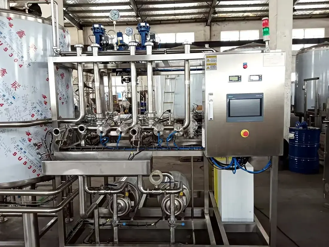
CIP systems
A CIP system is only as good as the circuit it serves. We design the circuits with the piping layout, check the return flow at the last valve, and record conductivity, temperature and flow so the cycle can be defended in an audit.
| Model | Tank volume | Pump | Power |
|---|---|---|---|
| LTCIP-0.5X3 | 0.5 m³ × 3 | 10 m³/h @ 32 m | 3 kW |
| LTCIP-0.8X3 | 0.8 m³ × 3 | 10 m³/h @ 32 m | 3 kW |
| LTCIP-1.0X3 | 1.0 m³ × 3 | 10 m³/h @ 32 m | 3 kW |
The three frames share one skid envelope: 3.2 × 1.4 × 1.6 m at 0.5 m³ and 5.5 × 1.8 × 2.1 m at 1.0 m³, weighing approximately 550–800 kg. Split-type systems from 1,000 to 10,000 L per tank, one to four circuits, for larger sections or several independent process areas.
| Step | Medium | Temperature | Verification |
|---|---|---|---|
| 1 | Pre-rinse | Ambient / 50 °C | Time, flow |
| 2 | Caustic | 60–80 °C | Conductivity, temperature |
| 3 | Intermediate rinse | Ambient–60 °C | Conductivity |
| 4 | Acid | 60–80 °C | Conductivity, temperature |
| 5 | Final rinse | Ambient | Conductivity, pH |
Disinfection is a separate pre-production step, not part of the standard five-tank programme. It requires a dedicated dosing tank and metering pump and is quoted as an option when the process requires it.
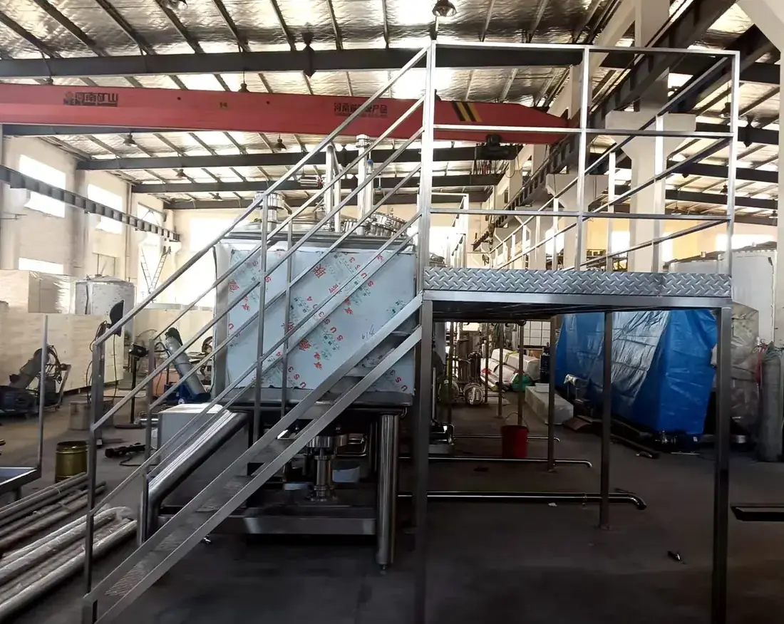
Installation & piping
Equipment standing on the floor is half a delivery. The fourth line is the work that connects it — sanitary product piping, in-section power piping, electrical cabinets and PLC programming — executed on site by our engineers as a priced scope, on the drawing set the equipment was built to.
- Same P&ID as the equipment — pipe routes, slopes and tie-in points are fixed while the equipment drawings are being made. Site time is for assembly, not for discovering that two valves have nowhere to sit.
- Product piping — orbital-welded sanitary spools, drainable slopes, valve clusters per circuit, weld log issued with the handover file.
- In-section power piping — steam, chilled water and compressed-air distribution inside the section, up to the tie-in points defined in the scope document.
- Electrical and automation — cabinets, cable, tray and field wiring; PLC + HMI programming with recipes, interlocks, alarm history and batch records.
- Packing and freight — export-grade packing, moisture- and shock-protected, freight terms stated per destination.
- Site execution — our own crew, or supervised local labour with remote support. Commissioning and operator training are ours either way.
| Work package | Content | How it is priced |
|---|---|---|
| Sanitary product piping | OD 25–127 mm spools, orbital welds, drainable routing, valve clusters per circuit | By route length and valve count from the P&ID |
| In-section power piping | Steam, chilled water and compressed-air distribution to the defined tie-in points | By circuit and pipe size |
| Electrical | Control cabinets, cable, tray and field wiring | By bill of quantities |
| Automation | PLC + HMI programming: recipes, interlocks, alarms, batch records | By I/O count and control loops; brand to your standard |
| Packing & freight | Export-grade packing, moisture- and shock-protected | Freight and Incoterms per destination |
| Site execution | Own crew, or supervised local labour with remote support | Man-days plus travel, stated before the order |
Installation is quoted as its own line rather than buried in the equipment price. That is what lets you compare two offers line by line — and add or drop the site work without renegotiating the machines.
What stays with you
The utility plants themselves — boiler, chiller, compressor — the building and civil work, and anything downstream of the process outlet. We define the tie-in points and the utilities we need; the plants are specified by others.
Around the three units.
These items are integrated into the section rather than sold as stand-alone product lines. They are sized from the same process data, which is why the deaerator is not oversized against the steriliser and the CIP circuit reaches the last valve.
Deaeration & flash treatment
Deaeration removes dissolved oxygen under vacuum — it protects flavour and shelf life, and it is not a sterilisation step. Flash treatment takes off a water fraction from concentrates. Both sit upstream of the steriliser and neither replaces it.
| Unit | Capacity | Evaporation | Dimensions (mm) | Power |
|---|---|---|---|---|
| Vacuum deaerator | 2–20 t/h | — | Per project | 10.35–35 kW |
| SZQ-5-A | 4–5 t/h | 250–320 kg/h | 2,100 × 1,200 × 3,200 | 12 kW |
| SZQ-10-A | 8–10 t/h | 510–650 kg/h | 2,700 × 1,250 × 3,500 | 14 kW |
Vacuum level −0.078 to −0.08 MPa with a 3 m² condenser. Aroma recovery is available as an option for aromatic products.
Heat exchangers, piping and control
- Plate heat exchangers — milk receiving coolers 1,000–30,000 L/h (1–30 m²); yogurt fermentation coolers 3,000–20,000 L (4–36 m²).
- Sanitary piping and valves — OD 25–127 mm, orbital-welded spools, drainable routing and valve clusters per circuit.
- Inline instruments — temperature, pressure, flow, conductivity and °Brix, selected to the control philosophy.
- Control — PLC + HMI with recipes, alarm history and batch records; remote support for commissioning.
- Homogenisers — integrated per project where the process chain includes homogenisation.
Scope boundary
Water treatment, filling and packaging, and post-filling sterilisation are not part of this scope — those are specified by others. Raw-material preparation upstream of blending is in scope: we build it where it is our own equipment, integrate a third-party unit where that is the better answer, and hold the interface either way.
Drawn before it is built.
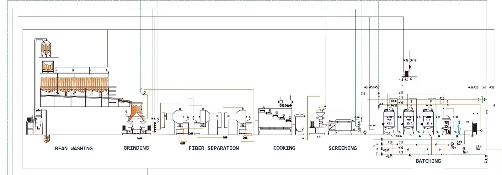
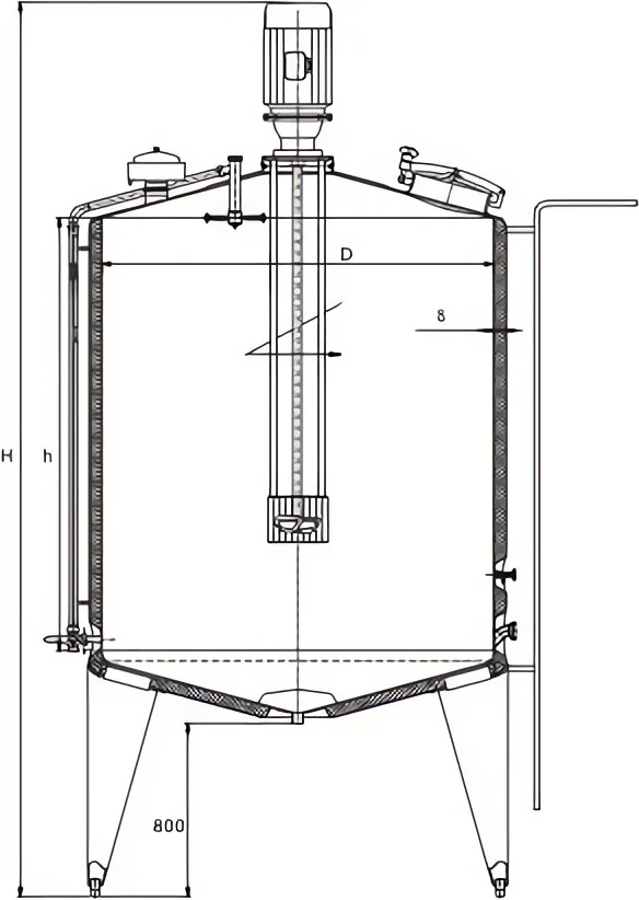
Every quotation is backed by drawings, not brochure pages: the vessel general arrangement you sign off before fabrication, and the section layout that fixes equipment positions, pipe routes and service interfaces before a single plate is cut. Two extracts from recent project documentation.
What comes with an order.
- Vessel general arrangements — nozzle schedule, overall and leg heights, jacket rating and centre of gravity, issued for your sign-off before fabrication starts.
- Section layout — equipment positions, pipe routes, utility connection points and maintenance access, coordinated with your building drawings.
- Interface list — every media, power and control connection the section needs, with position and size, so your installer prices it once instead of twice.
- As-built set at handover — drawings updated to what was actually built, in the same package as the DoC and the technical file.
Need a frame outside these ranges?
Most projects sit between standard frames. Send the process data and we will tell you which frame is closest, what changes inside it, and what the change costs.